It is time to create the first model of the airplane with
all the considerations taken before.
The surface of the fuselage is going to be created with two main sketches, horizontal (plan XY) and vertical (plan YZ). To find the intersection of these parallel plans with the sketches of the fuselage, vertical and horizontal straight lines are needed for creating intersections that will be start points. Then they will be united with curves drawn along parallel plans along the longitudinal axis Y so it will be formed by several sections, each section formed by 4 curves surfaces or fuselage plates. As it is symmetrical along axis X, just one curve is needed on each side and section, the symmetry will be applied later.
The surface of the fuselage is going to be created with two main sketches, horizontal (plan XY) and vertical (plan YZ). To find the intersection of these parallel plans with the sketches of the fuselage, vertical and horizontal straight lines are needed for creating intersections that will be start points. Then they will be united with curves drawn along parallel plans along the longitudinal axis Y so it will be formed by several sections, each section formed by 4 curves surfaces or fuselage plates. As it is symmetrical along axis X, just one curve is needed on each side and section, the symmetry will be applied later.

The two sketches are united by 7 section curves

Front view of these sections

All sketches and section curves conform the fuselage divided in 6 main parts
(24 in total)

Wing and tail are added (still without proper airfoils). Shark fin design is
aesthetic, as it could be the wing with sweep angle and winglets, but harder to
build.
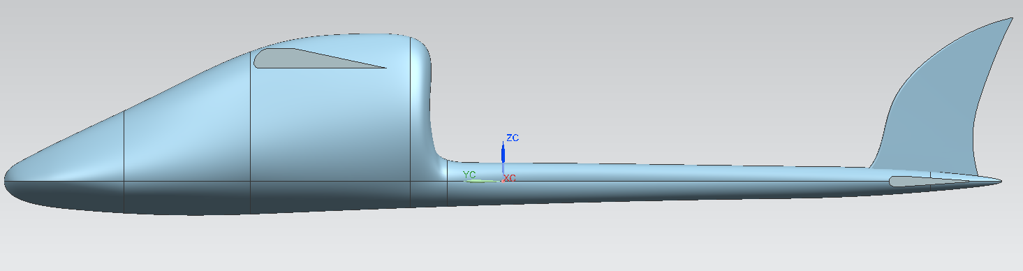
Side view of design 0.2
It can be appreciated that even with a high wing, the downwash may affect the
tail. The fuselage may also affect the vertical stabilizer.


Isometric view of design 0.3
Main landing gear, propeller, camera and gimbal are built. The ailerons take form. The landing gear still doesn’t protect the camera in case of collision.

Landing gear detail without bearings. Rigid rods transmit forces to fuselage
and wing. This camera has its own WiFi antenna
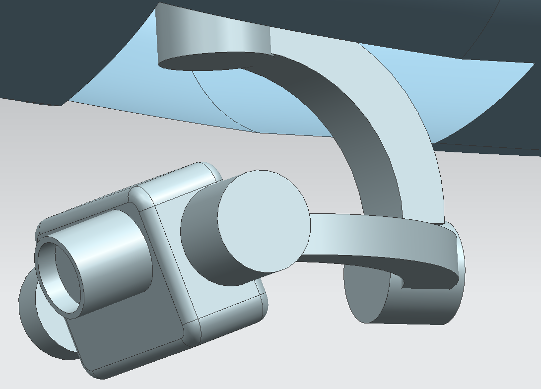
Camera and gimbal detail. It is a 3 axis gimbal with 3 brushless motors. Pitch
control covers from -130° to 90° and rolls from -45° to 45°.

Fuselage side cut
From the front to the rear, the gimbal is embedded in the
fuselage upwards to protect more the camera from possible crashes. It will be
glued or screwed to the main structure, with a big enough hole allowing the
free movement of the gimbal system. Then the battery is placed just below the
wing and as low as possible. The battery is going to feed the motor through the
ESC and the servos through the BEC system of the ESC, which controls that a
small amount of the battery is given with proper voltage to the servos’ motors.
The battery and ESC must be placed next to each other, but the ESC must be
placed a bit to the rear too to reach not only the servos of the wing but those
in the tail too. Between the servos and the ESC, a gyro system circuit board is
supposed to control the surfaces to compensate turbulences and unexpected wing
forces that disturb the plane’s flight, so extension cables might be needed to
reach the servos. The further back these components are placed, the better,
because there is already a lot of weight from the camera in the front.
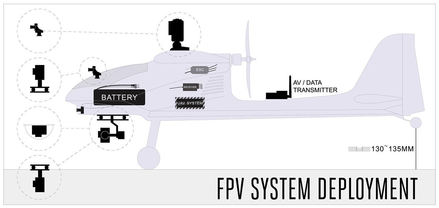
This scheme of the Ranger Ex Platform gives an idea of a
more detailed study of the components relative position:
The following designs of the plane have all improvements of
its parts, either for making it more realistic, efficient or easier to
manufacture.
The landing gear is put a bit forward to protect the camera.
The single wheel is added to the back of the plane to complete de landing gear.
The propeller and motor models are improved, as well as the gimbal and the
union between main fuselage and the tail. Other bodies changed from solids to
surfaces for a first fluid simulation.

Side view of design 0.4
The airfoil E374 conforms the detailed wing structure. The
coordinates for this airfoil are taken from airfoiltools.com and plotted as a
spline in NX, then extruded. The ailerons are formed almost at the tip of the
wing with a rib of separation from the edge. There are two thin rods that
connect the ailerons to the wing and allow their independent rotation around
it.

One-piece E374 wing with ailerons and rounded edges

Aileron hinge detail
The horizontal stabilizer uses a symmetric airfoil, the NACA
0012.

Just as the wing is made, the horizontal stabilizer is built
The vertical stabilizer changes to a more common shape which
is stronger, easier for manufacturing and controlling the yaw movement. For the
moment it still has a symmetric cut but not a formalized airfoil, just straight
lines and arcs at the front. The thin rod inside joins the rudder surface to
the stabilizer, allowing it to freely rotate around it.

Vertical stabilizer side view
The next design has a formalized landing gear structure. The
main landing gear is designed according to existing wheels and mounting, as
well as the tail connection, all of them available at local stores.
A new propeller is used now, with much more aerodynamic and realistic blades modelled in 4 quarters out of splines, tangent on the front and rear plans.
The wings are cut in two, the same way they will be manufactured and mounted on the plane, one attached to each side of the top fuselage. Their tips are flattened to follow the shape of the tip rib and the holes for the rod are correctly made to sew all the surfaces together.
The fuselage part joining the front and the tail is removed and replaced by a long and strong rod.

Isometric view of design 1.1

Formalized main landing gear

Formalized tail landing gear

10x6 inches propeller blades
All remaining solids are turn to surfaces with some remodeling.
The motor is pulled back, out of the fuselage, and installed in a mount. The main
wheels bearings are improved.

Motor mounting

Landing gear detail
There is one issue with the propeller and it is the fuselage
that blocks the inlet air to the bottom part of the propeller, so that part
will have its thrust reduced. A simple solution is to open holes in the foam
that work as air inlet, taken from the uniform current directly to the
propeller blades. The rigid structure of the back of the fuselage will be
weaker but he motor will push more.


Although the structure has aerodynamic efficient curves, the
available machines can’t cut that way, they just can approximate the smoothness
with several straight lines.
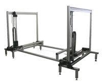


The fuselage must be optimized for manufacturing. The hot
wire 4-axis cutting machine cuts the foam block in straight lines because the
wire is tense and such is the way it is modelled now. This design includes an
FPV camera too, apart from the camera mount below the fuselage, and it will be
located at the foremost part of the fuselage to create a cockpit environment. The
plastic cover protects the camera in case of crash and reduces the drag with
the air flow.

.jpg)
Example of a nose with a big camera and a plastic case
http://www.hobbyking.com/hobbyking/store/__38072__HobbyKing_174_8482_Go_Discover_FPV_Plane_EPO_1600mm_PNF_.html
Again, from scratch, two main sketches are made, horizontal
and vertical. The plant shape must be wide not only to hold the components such
as the battery, 50 mm wide, but to have wide walls of foam that give strength
to the plane. At the nose of the plane, a hemispherical shape is needed to
place the cover of the FPV camera. It will have big enough dimensions to hold,
in case of need, one of the biggest cameras considered and a pan/tilt
mechanism.

XY sketch
The top line of the vertical sketch is the most critical. Its
shape has big repercussions on the total drag of the fuselage. The last version
of the fuselage had 635 mm of length. Taking out the peak of the nose and the
rounded back that is not properly manufactured in the simulation, the length is
600 mm, easily divided in parts of 200 mm. Once the configuration is fixed for
3 blocks with the same width, the angles of the straight lines are set with the
help of the shadow from the previous fuselage to be as similar as possible and
a reference arc in red which gives an approximate shape of the smoother lines
that help the air flow stay close to the plane and not to become detached. If
these vertices are too sharp the plane will need a more powerful motor.
The bottom lines are made tangent to the camera cover too and adjusted to join the middle rod of the fuselage. Being straight help the fixation with the landing gear and the gimbal.
The bottom lines are made tangent to the camera cover too and adjusted to join the middle rod of the fuselage. Being straight help the fixation with the landing gear and the gimbal.

YZ sketch. Red arc is tangent to the air flow and camera cover.
Then the transversal sketches join the two sketches through
the intersections of those with the plans, creating the side shape of the
blocks that the wire will cut.

XZ sketches
Thanks to the sketches the surfaces are created one by one,
simpler than before, and made symmetrical. The rest of the fuselage is formed
by the union rod and a small part at the rear that will hold the tail elements.

Isometric view of the fuselage design 1.4
Adding the main parts completes the configuration.

Isometric view of design 1.4 with main parts.
Hi Sergio, great work!
ReplyDeleteI'm interested in your work, i work with a Ranger for my degree final project.
I want to run CFD simulate with the Ranger Volantex, you upload de CAD model to any platform?
or, you can send me the files?
My final objective is construct the dynamical model for this airmodel and test control algorithms.
Thanks
Guillermo Sánchez Herrera
Est. Mechatronics Engineering
National University of Colombia
Hi! Sorry for the late response. I didn't really model the Volantex Ranger but a similar model from scratch I thought to be optimal. The thing is it finally turned out to be very similar to Volantex Ranger.
DeleteAdditionallyy, I stopped updating this blog when I run out of time to make all the analysis but I didn't made a proper CFD analyis.
Is there anything else I can help you with?
good.
ReplyDeleteI am a student of the Isthmus Technological Institute and I am involved in a research project by the Mexican Academy of Sciences and I wanted to see if you can provide me with the CAD file of the airplane to do tests and with that you would help me a lot in my work.
First of all, Thanks.